Making an HPLC Sample Injection Loop

IonSource home | disclaimer


HPLC Tubing Volume Calculator

ID of tube (mm) length of tube (cm)  


"an IonSource tutorial"

Make Your Own HPLC Sample Injection Loop 
including the topic 
Determining HPLC System Dead Volume


IonSource Home | disclaimer


Introduction

-

The injection loop is a critical component of an HPLC and is potentially one of the largest sources of excess HPLC system volume.  The sample is injected into the loop while the loop is switched out of the HPLC flow path.  After the loop is filled with sample it is switched back into the flow path and the sample is swept onto the head of the HPLC column for later elution or the sample is injected directly into a mass spectrometer as part of a flow injection analysis.

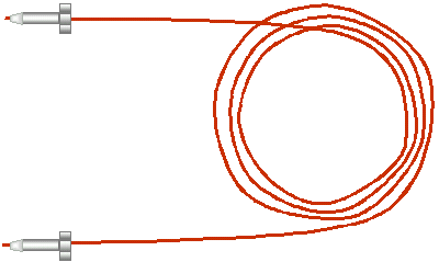
PEEK™  Loop

.
.

Injection Loop Dimensions

.

Loop dimensions are important.  The most accurate injections are made with a technique known as overfilling.  When using the overfill technique a sample injection will be made that is 3 to 5 times larger than the volume of the injection loop.  This is done because the core of an injection plug travels faster than the outer perimeter of the injection and if one tries to make, for example, a 100 µL injection onto a 100 µL loop it is likely that the core of that sample injection will over shoot the end of the loop and go to waste.  An overfill ensures that the loop is completely filled and will inject a precise amount, the exact volume of the loop.  Overfilling is fine if the sample amount is unlimited.  However if you are performing a characterization of a rare species the thought of sending any of that sample to waste is very very scary.  Often when the sample is limited an under fill of the sample loop is performed.

Optimizing the loop volume for the injection is important.  The loop can be a significant source of HPLC system dead volume.  There is no reason to have a 1 mL loop when the injection volume is 10 µLs.  A large loop volume will delay the peak and possibly adversely affect your chromatography.  For a proper under fill, 10 µLs of a precious sample can be safely made onto a 25 µL loop.  In this latter example the tailored loop volume helps to cut down on surface area, where a dilute sample may adsorb, and also helps to improve the chromatography.  In addition if the HPLC flow rate is low, 25 to 10 µL/min, it is generally better to keep the internal diameter of the injection loop low, preferably below 125 µM to aid in efficient evacuation of the loop.

 .

.

Making a Sample Injection Loop

-
An HPLC loop of any dimension is easy to make.  The loop can be constructed of  HPLC steel tubing, fused silica, or (our choice) PEEK  tubing.  We use PEEK tubing because it is easy to cut to size and flexible and it is easily fitted with "finger tight " nuts and ferrules.  PEEK™  tubing is also resistant to most organic solvents and can withstand pressures to 5000 psi..  Use the script (form) at the top of this page to calculate the volume for a specific length of tubing in the preparation of an injection loop.

.

When making partial fill loops where sample conservation is key we recommend a loop that is 2.5 times the injection volume.  To make a 10 µL injection one should make a 25 µL injection loop.

Determining HPLC Dead Volume

Determining the HPLC system dead volume is pretty straight forward.  First replace the HPLC column with a zero dead volume union.  Make a small  injection of  a UV absorbing solvent.  Inspect the resulting chromatogram to determine how long it took the injection to get through the HPLC.  This peak is sometimes called the front, or break through or flow through peak.  If the flow through peak takes 2 minutes to get through the HPLC at a flow rate of 1 mL/min the dead volume is 2 mL.   Determining the source of the dead volume is not always easy.  For the sample it will include the volume of the injection valve, the injection loop and the tubing that leads to the column and then the tubing from the column to the detector.  As mentioned above the HPLC injection loop can be a major source of dead volume.  Next one should address the tubing lengths leading to and away from the column.  The tubing leading away from the column will have the biggest impact on the peak dilution so this is where optimizing length and volume is critical.  Remember, mass spectrometers as well as UV detectors are concentration dependant detectors.  One can use the script at the top of this page to calculate HPLC tubing volumes.  Gradient delay, or how long it takes the gradient to reach the head of the column and begin the elution of the analyte is also critical.  Components involved in gradient delay will include the mixer, pulse dampener, tubing between these devices and tubing leading to the injection valve.  On some systems the static mixer can be removed to eliminate dead volume.  Any modification to an HPLC will need to be evaluated by the operator and may be subject to change control and revalidation if the laboratory is cGMP compliant.

Note:PEEK (polyetheretherketone) is a registered trade mark of Victrex plc.
 

home | disclaimer
Copyright © 2000-2016  IonSource  All rights reserved. 
Last updated:  Saturday, July 09, 2016 02:18:28 PM